Mill Cutter Compensation
Control compensation is only applied for finishing passes.
In ECAM there are 3 compensation mode available :

Computer Mode
This is the most compatible mode, since all the final path is calculated automatically. The output code don't contains any command related to compensation ( usually G41 - G42 )
But it's not possible adjust the toolpath by the tool corrector table. If don't have to worry about setting tool diameter in Tool Diameter register.
So it's not indicate if you have to keep tight tolerances in your workpiece.
See at bottom page for info about output code .
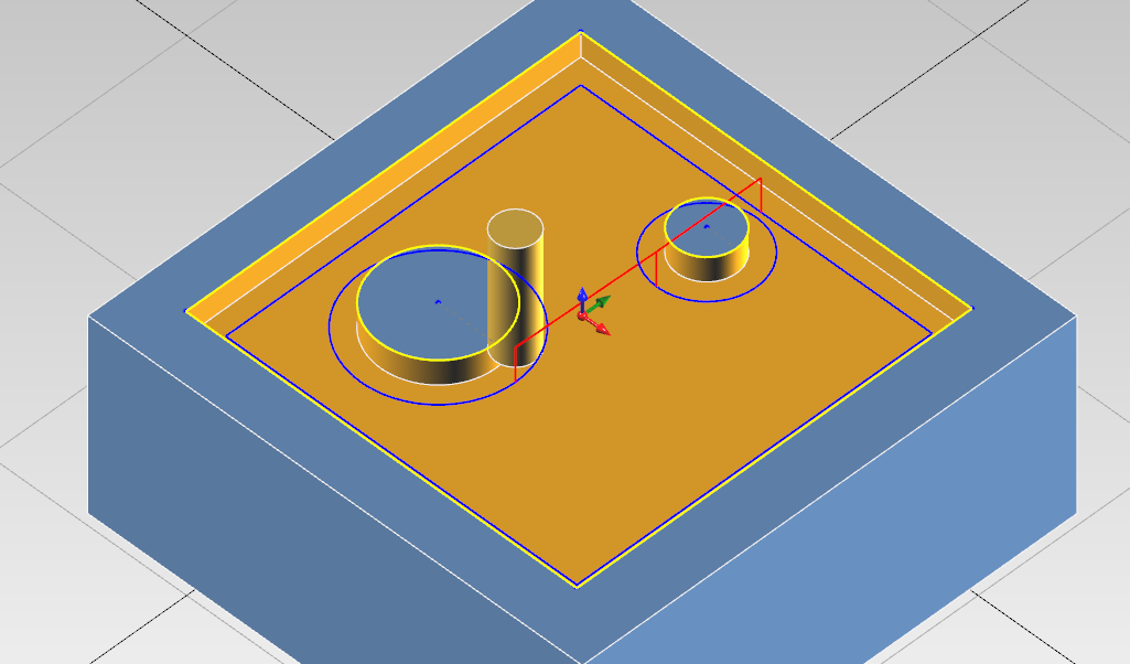
Computer Compensation Mode:
CNC Mode
This the least compatible mode. The output path reflect exaclty the geometry profile. All the offset are calculated by the cnc machine.
A approach move is necessary to enable tool compensation.
In the output code are present code for enabling / disabling cutter compensation (usually G41/G42/G40).
The linear approach movement is 20% more than the tool diameter. At now is only possible do this movement at secure z and then after the radius comp. is on , move to work z with plunge feed.
Here is necessary to set the tool diameter in cnc tool register, and adjust it if is necessary to compensate the tool deviation.
The toolpath preview show always the uncompensated path. This issue can be misleading in CNC Compensation Mode.
See at bottom page for info about output code .
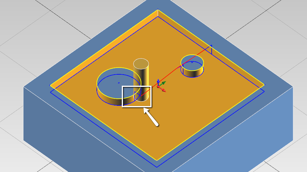
CNC Compensation Mode:
Tool Wear Mode
From my point of view, this is the most versatile mode.
The offset diameter is calculated by the computer, but you can adjust the toolpath anyway ny editing the tool wear registry in cnc machine.
This permits to have less incompatibility issues with cnc.
In the output code are present code for enabling / disabling cutter compensation (usually G41/G42/G40).
One downside is you have to use end-mill with the same diameter used in ecam. But it's not a big deal since you can synchronize quickly the generated code and upload to machine.
See at bottom page for info about output code .
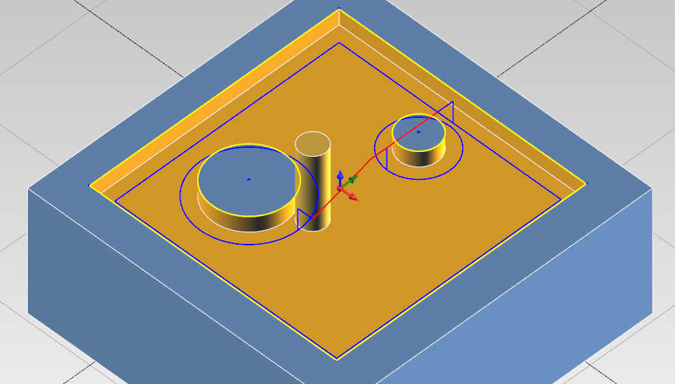
Tool Wear Compensation Mode:
Output Code
To help the machininst have clear what compensation is enabled and what values has to insert in cnc tool registry, in the output code are visible all this information.
Both in tool summary and when the tool is actually called.
Computer Compensation Example :
Tool Summary :
(#7 - END MILL D 8MM COMP COMPUTER - RADIUS COR VALUE 0)
Tool Called :
N5
(POCKET - FINISHING)
(COMP COMPUTER - RADIUS CORRECTOR VALUE 0)
(END MILL D 8MM)
CNC Compensation Example :
Tool Summary :
(#7 - END MILL D 8MM COMP NCCONTROL - RADIUS COR VALUE 4)
Tool Called :
N5
(POCKET - FINISHING)
(COMP NCCONTROL - RADIUS CORRECTOR VALUE 4)
(END MILL D 8MM)
Tool Wear Example :
Tool Summary :
(#7 - END MILL D 8MM COMP TOOLWEAR - RADIUS COR VALUE 0)
Tool Called :
N5
(POCKET - FINISHING)
(COMP TOOLWEAR - RADIUS CORRECTOR VALUE 0)
(END MILL D 8MM)
You can see what compensation mode is going to be activated , and what value have the machinist have to insert in the registry.
From this comments ,you have to set the tool diameter only with CNC Compensation, with the other two modes you have to set to 0 the tool diameter.
G-Code Customization
See also this for more detail of output code customization.